Tutorials
These tutorials should introduce you to the major concepts you need to build and use your own IOTile Devices. They don’t require any special hardware to run, just a computer with CoreTools installed.
Creating Your First IOTile Device
There are two kinds of IOTile Devices, real and virtual. Real devices are physical objects that let you either sense or control things around you. Virtual devices are programs that act as if they are real IOTile Devices.
Virtual devices are indistinguishable from real IOTile devices, except for the fact that you can’t actually touch them. In particular, virtual IOTile devices interact with the rest of CoreTools the same way a real device would, so they are particularly useful for tutorials like this one.
We’re going to make a simple virtual IOTile Device that will stream you fake temperature data when you connect to it. It will also have one command that will send you a random temperature value back to you whatever you call it. Then we’re going to interact with the device as if it were a real IOTile device.
Goals
- Introduce the concept of Python Proxy Modules, that are used to wrap low-level access to IOTile devices in a python compatible API
- Introduce Virtual Devices and show how you can use them to quickly mock up what a real IOTile device could look like and use them with the rest of CoreTools.
- Introduce Support Packages, which are pip installable packages that contain all of the necessary python modules to interact with an IOTile Device. They are usually produced as part of the build process for the device.
Note
For this tutorial, you are going to need to have CoreTools installed. It’s best to create a new virtual environment for this walkthrough so that you have a clean slate and don’t pollute any other CoreTools installations you have with the products of this walkthrough.
Background
When you send commands to an IOTile device, the commands all take the form of remote procedure calls (RPCs). Basically you send an ID indicating what function you want the device to execute, followed by the arguments. The device synchronously executes the function and returns the response back to you as if you had just invoked a function locally on your own computer.
Since IOTile devices typically contain small embedded microcontrollers, the low-level binary encoding for how RPCs are transmitted to the device is not user-friendly, e.g. the RPCs are identified with unique 16-bit numbers rather than string names and all arguments and responses are packed into 20 byte binary buffers.
So, instead of directly building these low-level RPC payloads and manually decoding the responses, CoreTools wraps them inside a python class where the methods on the class take in normal python objects as arguments, build the RPC payload and decode the response back into normal python objects. These wrappers are called Proxy Objects and the python modules that contain them are called Python Proxy Modules.
Every IOTile device should have at least one python proxy module that allows you to access its functionality from python. Many IOTile devices internally consist of several distinct parts called Tiles, each of which is independent and has its own proxy module. For now though, we won’t have to worry about multiple proxy modules.
The goal of this tutorial is walk you through creating a proxy module. Rather than wrapping a physical IOTile device though, we’ll wrap a virtual device so you don’t need any hardware to follow the walk through.
Getting Started
Before we can start working on our proxy module, we first need to get some boilerplate out of the way. We need to create an IOTile component that will contain our proxy module.
Important
Pretty much everything in the IOTile world (except CoreTools itself) starts its life as an IOTile Component.
Components are like packages in npm, or distributions in PyPI. They are just directories with a
module_settings.json file that lets CoreTools know what to do with the files inside the folder.
So, let’s create an empty Component to contain our proxy module:
$ mkdir test_component
$ cd test_component
$ mkdir python
$ touch python/demo_proxy.py
$ touch module_settings.json
$ ls
module_settings.json    python
Now we need to add enough information to module_settings.json to identify this folder as an IOTile component and
point out that demo_proxy.py should be treated as a proxy module. We’ll call our component demo_component and
put it in the walkthrough namespace (called a domain). These names can be anything but should be unique if you
ever want to share your component with anyone else.
Save the following to your module_settings.json file:
{
    "module_name": "demo_component",
    "modules":
    {
        "demo_component":
        {
            "version": "0.0.1",

            "products":
            {
                "python/demo_proxy.py": "proxy_module"
            },

            "domain": "walkthrough"
        }
    }
}
This is the minimum needed in a module_settings.json file to identify the component and point out that we have a proxy
module defined in python/demo_proxy.py. In more complicated components, there are many different kinds of products that
could be generated and would be listed along with the proxy module in the products section of the file.
Now that we have an IOTile component, we need to tell CoreTools about it by adding it to the Component Registry (this command
should be run from the test_component directory:
$ iotile registry add_component .
$ iotile registry list_components
walkthroughs/demo_component
Important
The Component Registry is a file maintained in each virtualenv that contains a CoreTools installation. It lists what iotile components have been installed so that CoreTools knows to look in those directories for things like proxy modules.
Any changes you make to your Component Registry only affect your current virtual environment.
Now you have your component registered with CoreTools so we need to create a simple virtual device that it can interact with.
Creating a Virtual Device
Virtual IOTile devices are just python scripts that define a class that inherits from BaseVirtualDevice. We’re going to
create a demo device. Just like above there is a bit of boilerplate that is required for the device to support the necessary
RPC for CoreTools be able to identify its name and match it with a Proxy Module. Since the device we are creating is so
simple, we are going to derive from a convenience subclass SimpleVirtualDevice.
Create a file named demo_device.py in your current working directory with the following contents:
"""Virtual IOTile device for CoreTools Walkthrough"""

from iotile.core.hw.virtual import SimpleVirtualDevice, rpc


class DemoVirtualDevice(SimpleVirtualDevice):
    """A simple virtual IOTile device that has an RPC to read fake temperature

    Args:
        args (dict): Any arguments that you want to pass to create this device.
    """

    def __init__(self, args):
        super(DemoVirtualDevice, self).__init__(1, 'Demo01')
Note how this is just a normal python class and it has one function controller_status that is
decorated with an @rpc decorator. This decorator is how we mark what python functions in our
class are really mocking the RPCs present in a real IOTile device. For more information on the rpc
decorator, we can see its documentation below.
-
iotile.core.hw.virtual.rpc(address, rpc_id, arg_format, resp_format=None)[source]¶ Decorator to denote that a function implements an RPC with the given ID and address.
The underlying function should be a member function that will take individual parameters after the RPC payload has been decoded according to arg_format.
Arguments to the function are decoded from the 20 byte RPC argument payload according to arg_format, which should be a format string that can be passed to struct.unpack.
Similarly, the function being decorated should return an iterable of results that will be encoded into a 20 byte response buffer by struct.pack using resp_format as the format string.
The RPC will respond as if it were implemented by a tile at address
addressand the 16-bit RPC idrpc_id.Parameters: - address (int) – The address of the mock tile this RPC is for
- rpc_id (int) – The number of the RPC
- arg_format (string) – a struct format code (without the <) for the parameter format for this RPC. This format code may include the final character V, which means that it expects a variable length bytearray.
- resp_format (string) – an optional format code (without the <) for the response format for this RPC. This format code may include the final character V, which means that it expects a variable length bytearray.
There are a couple of other things to note about our DemoVirtualDevice. We gave it a name of Demo01. All IOTile
devices have a 6 character name that is used to match the device with its associated proxy module by looking for matching
names. We also gave the device an IOTile ID of 1, which we’ll use to connect to the device.
So, let’s try to interact with our virtual device:
$ iotile hw --port=virtual:./demo_device.py
(HardwareManager) connect 1
(HardwareManager) controller
HardwareError: Could not find proxy object for tile
Additional Information:
known_names: ['Simple', 'NO APP', 'Rptdev']
name: 'Demo01'
(HardwareManager) quit
$
We told the iotile tool that we wanted to connect to an IOTile device that was virtual and implemented in the python module
./demo_device.py. We connected to it (connect 1) and tried to get a proxy object for it using the controller
command but we were told that CoreTools couldn’t find a proxy module for it.
This makes sense because we haven’t created the proxy module yet. So, lets create a basic proxy module and try again. Add the
following to demo_proxy.py (make sure this file is within the python subfolder):
from iotile.core.hw.proxy.proxy import TileBusProxyObject
from typedargs.annotate import return_type, context, param
import struct

@context("DemoProxy")
class DemoProxyObject(TileBusProxyObject):
    """A demo proxy object for the CoreTools walkthrough"""

    @classmethod
    def ModuleName(cls):
        """The 6 byte name by which CoreTools matches us with an IOTile Device"""

        return 'Demo01'
The only required function that we need to implement is the classmethod ModuleName that tells CoreTools what IOTile devices
should load this proxy module. Now let’s try to connect to our virtual device again:
$ iotile hw --port=virtual:./demo_device.py connect 1 controller
(DemoProxy) quit
$
This time CoreTools looked through the registry and found a matching proxy object (our DemoProxy object). Now we’re ready to start adding some functions to our virtual device and wrapping them in the proxy object so we can test them out from the command line.
Adding an RPC That Returns Data
Let’s add an RPC to our virtual device name get_temperature that returns the (fake) temperature of the device. Add the following to
your demo_device.py DemoVirtualDevice class:
@rpc(8, 0x8000, "", "L")
def get_temperature(self):
    """Get the current temperature of the device in degrees kelvin

    Returns:
        list  a list with a single value containing the device temperature
    """

    return [273]
This defines an RPC with id 0x8000 that returns a single 32-bit integer (the L result format) with the fixed value 273. Now we
need to add a function to our proxy object that calls this RPC.
Note
The rpc decorator, as described in the doc source above, is how we pack and unpack data types
through struct under the hood. You’ll see this later, but there are several ways to communicate
more information, as long as you fit in 20 byte payloads.
For example, you can pack something with 10s, and you pass in a length 10 string.
Add the following to your demo_proxy.py DemoProxyObject class:
@return_type("float")
def get_temperature(self):
    temp, = self.rpc(0x80, 0x00, result_format="L")
    return float(temp)
Note
The decorator on this function is what allows iotile to print the function’s return value on the command line. There is more information
about these type annotations in the section on typedargs.
Now let’s call our new RPC:
$ iotile hw --port=virtual:./demo_device.py connect 1 controller
(DemoProxy) <TAB><TAB>
back              config_manager    hardware_version  quit              status            tile_status
check_hardware    get_temperature   help              reset             tile_name         tile_version
(DemoProxy) get_temperature
273.0
(DemoProxy) quit
$
Internally this worked because our type annotation in DemoProxyObject told the iotile tool that this function could be called from the command
line. So when we typed get_temperature we invoked that function in DemoProxyObject. Internally it used the self.rpc function provided
by TileBusProxyObject to invoke an RPC on our virtual device, which sent back the temperature value 273 that it then returned and iotile
printed for us using the return_type type annotation to know that we wanted it to print the result as a floating point number.
If we had been talking to a physical IOTile device rather than a virtual one, nothing would be different except for the argument that we passed to
--port in HardwareManager that tells it what transport mechanism to use to send RPCs and receive their responses.
Adding a More Complex RPC
Let’s say that our device actually can store the last 5 temperature values that its recorded and has an RPC that allows us to query them all. We want to print those values as a list. First lets implement the underlying RPC on the virtual device:
@rpc(8, 0x8001, "", "LLLLL")
def historical_temps(self):
    """Get a list of 5 temperatures from the device in degrees kelvin

    Returns:
        list  a list with a single value containing the device temperature
    """

    return [273, 280, 215, 315, 300]
Then we need to add a corresponding call on the proxy object:
@return_type("list(float)")
def historical_temps(self):
    temps = self.rpc(0x80, 0x01, result_format="LLLLL")
    return [float(x) for x in temps]
Note
See how we used a complex type annotations list(float) to tell typedargs how to print our return value even though it wasn’t
a simple primitive type.
Now we can call it:
$ iotile hw --port=virtual:./demo_device.py connect 1 controller
(DemoProxy) historical_temps
273.0
280.0
215.0
315.0
300.0
(DemoProxy) quit
$
Setting Values Using an RPC
Up until now, we’ve only received information from RPCs, so lets create one that lets us set the temperature that the virtual device returns when you
call get_temperature. We’ll need to create a member variable to store the temperature and a new RPC set_temperature that sets its value. Adjust
demo_device.py to look like this:
"""Virtual IOTile device for CoreTools Walkthrough"""

from iotile.core.hw.virtual import SimpleVirtualDevice, rpc


class DemoVirtualDevice(SimpleVirtualDevice):
    """A simple virtual IOTile device that has an RPC to read fake temperature

    Args:
        args (dict): Any arguments that you want to pass to create this device.
    """

    def __init__(self, args):
        super(DemoVirtualDevice, self).__init__(1, 'Demo01')
        self.temp = 273

    @rpc(8, 0x8000, "", "L")
    def get_temperature(self):
        """Get the current temperature of the device in degrees kelvin

        Returns:
            list  a list with a single value containing the device temperature
        """

        return [self.temp]

    @rpc(8, 0x8002, "L")
    def set_temperature(self, new_temp):
        """Set the current temperature of the device in degrees kelvin"""

        self.temp = new_temp
        return []

    @rpc(8, 0x8001, "", "LLLLL")
    def historical_temps(self):
        """Get a list of 5 temperatures from the device in degrees kelvin

        Returns:
            list: a list with 5 historical temperatures
        """

        return [273, 280, 215, 315, 300]
Now add a new annotated RPC wrapper to DemoProxyObject in your demo_proxy.py file:
@param("new_temp", "integer")
def set_temperature(self, new_temp):

    self.rpc(0x80, 0x02, new_temp, arg_format="L", result_format="")
Important
When you write a proxy module method that takes arguments, you need to
tell typedargs what type they are so that it can convert them to the
appropriate python types when you enter them on the command line. In this
case we’re telling typedargs that we take one parameter new_temp
that is an integer. That’s all we need to say and typedargs takes
care of interpreting our command line input into a native python integer
and passing that to set_temperature.
Alternatively, you can pack your arguments with the newer rpc method, rpc_v2:
@param("new_temp", "integer")
def set_temperature(self, new_temp):

    self.rpc_v2(0x8002, "L", "", new_temp)
Note that here, the rpc_id is combined in to one argument, and you are required to pass two arguments ahead
of your input: the arg_format (in this case, L ), and the resp_format, which in this case is blank.
If you provide multiple inputs you would append an argument for each format type, for example:
self.rpc_v2(0x8888, "LLL", "", new_temp1, new_temp2, new_temp3)
Additionally, you could use @docannotate instead of @param to tell typedargs how to parse input:
@docannotate
def set_temperature(self, new_temp):
"""Sets the temperature of the virtual device.

Args:
    new_temp (int): New temperature
"""
    args = struct.pack("<L", new_temp)

    self.rpc(0x80, 0x02, args)
Let’s try out our set_temperature and get_temperature functions:
$ iotile hw --port=virtual:./demo_device.py connect 1 controller
(DemoProxy) get_temperature
273.0
(DemoProxy) set_temperature 15
(DemoProxy) get_temperature
15.0
(DemoProxy) set_temperature 275
(DemoProxy) get_temperature
275.0
(DemoProxy) quit
$
Next Steps
This concludes the tutorial on creating proxy modules. It’s a pretty simple proxy module that we made that just sets one number but one of the core principles of IOTile is that everything we do should be as reusable as possible, so in future tutorials we’ll take the exact same proxy module and virtual device and show how you can access them over MQTT from anywhere in the world or over Bluetooth Low Energy without doing any additional work.
You may already be able to think of what you would want to do with a virtual device running on your computer that would let you run a python function from anywhere in the world.
Understanding IOTile Reports
All data from IOTile devices comes in the form of Reports. As the name suggests, a Report just contains a list of data that the IOTile Device wants to report to the cloud. This data is packed into a specific structure for transportation to the cloud and then unpacked and inspected to make sure it arrived correctly and originated from the IOTile Device that it claimed to come from.
In this tutorial, we’re going to build our own reports in Python to get a feel for how the process works and the various classes involved.
At the end we’ll talk about how you could upload a report to the cloud on behalf of a device.
Goals
- Understand how IOTile devices report data and how they package it into reports for transmission.
- Introduce the classes in iotile-core that represent data from IOTile devices and their API.
- Understand the distinction between realtime data and signed Robust Reports.
Background
Before talking about how CoreTools handles data from IOTile Devices, we need to cover how IOTile Devices generate data in the first place.
IOTile Devices are designed to produce timeseries of discrete data points. Think of a soil moisture sensor programmed to record the water content in the soil every 10 minutes. It produces a single data stream which is a series of discrete soil moisture readings (i.e. single numbers) every 10 minutes.
Now think of a more complicated IOTile Device that measures soil moisture every 10 minutes but also measures the temperature of the air every hour and wants to report both of those numbers. Clearly, there needs to be a way to distinguish these two data streams so that users know which numbers are temperatures and which are moisture values.
IOTile Devices distinguish different sensor readings by using a 16-bit Stream identifier (a Stream ID), where each different Stream corresponds to a different type of reading.
All of the data entries in a Stream are time, value pairs, i.e a single reading that occurred at a specific time. Most IOTile Devices timestamp their data with 1 second precision. Currently, each data value saved in a Stream must fit in 32 bits, so it can either be an integer or encoded/packed into an integer.
For example, realtime water flow measurements might report their results as 2 16 bit numbers packed together with one number representing the fractional part of the flow and the other number representing the whole number part of the flow (a 16.16 fixed point format).
To save space on small embedded microcontrollers, there are no explicit units included in data sent from IOTile Devices.
Important
it us up to the user to make sure that they understand the implicit units of the data being sent from an IOTile Device, since just bare numbers are transmitted from the devices. The data in each Stream must all have the same units.
Since many IOTile devices are not directly connected to the internet, they typically save up data to transmit periodically to the cloud in the form of a Report. A Report is simply a data packet with 1 or more readings in it and some associated header and footer information identifying where it came from and what it contains. Reports may be encrypted or cryptographically signed if desired to provide data privacy and verification of origin.
Key Concepts
- Reading
- An individual time/value data entry recorded by an IOTile Device. Each reading is timestamped and the reading value must fit in 4 bytes (32 bits). Every reading must be associated with exactly 1 Stream.
- Stream
- A time series of Readings that all have the same units and should be logically grouped together. Usually Streams come from a single sensor.
- Stream ID
- A 16-bit number that identifies a stream. Stream IDs are stored with each Reading so that the device can remember what Stream that Reading is contained in.
- Report
A Report is a data packet containing one or more Readings from one or more Streams that is packaged together for transmission from an IOTile Device to a remote user, usually either a mobile phone or the cloud.
There are different report formats that can be used depending on the communication channel constraints and the user’s desired privacy and security levels for the data.
How CoreTools Handles Reports
Once data is received from an IOTile Device, it is decoded into an IOTileReport subclass. All reports processed through CoreTools are represented as subclasses of IOTileReport.
Each IOTileReport contains one or more IOTileReadings which are the way that CoreTools represents Readings coming from an IOTile Device.
The IOTileReading class is pretty simple.
-
class
iotile.core.hw.reports.IOTileReading(raw_time, stream, value, time_base=None, reading_id=None, reading_time=None)[source]¶ Base class for readings streamed from IOTile device.
Each reading represents a single time/value pair sent from an IOTile Device. Since many IOTile Devices do not have a hardware realtime clock, the timestamp that is assigned to a reading may only be a relative interval from a fixed event in the past, like the time the device turned on.
If the user knows the absolute time for this event they can pass it as a datetime in time_base to turn the relative reading timestamp into an absolute datetime accessible as reading_time.
Parameters: - raw_time (int) – the number of seconds since the device turned on when the reading was taken
- time_base (datetime) – An optional estimate of when the device was last turned on so that we can calculate the actual time of the reading
- reading_time (datetime) – An optional UTC time when this event was acquired. If combined with time_base, this value will take precedence and time_base and raw_time will be ignored.
- reading_id (int) – An optional unique identifier for this reading that allows deduplication. If no reading id is passed, InvalidReadingID is used.
- stream (int) – The stream that this reading is part of
- value (int) – The raw reading value
-
classmethod
FromDict(obj)[source]¶ Create an IOTileReading from the result of a previous call to asdict().
Parameters: obj (dict) – A dictionary produced by a call to IOTileReading.asdict() Returns: The converted IOTileReading object. Return type: IOTileReading
There are two major Report Formats that we are going to be using in this tutorial. The first is the IndividualReportFormat. Individual reports contain a single reading and are used by IOTile devices to communicate real time data to a connected user that should not be stored persistently in the cloud.
Important
Readings sent in Individual reports cannot be stored persistently in iotile.cloud since they do not contain the required unique reading identifiers to allow the cloud to deduplicate readings received from multiple sources. They are only used for transmitting ephemeral, realtime data.
The second major report format is the SignedListReport. Signed list reports, as the name suggests contain a list of readings, possibly from multiple streams and can be cryptographically signed to ensure that they came from the device they claim to come from.
Simulating Realtime Data
Note
This section builds on the virtual device concepts we used in the first tutorial on Creating Your First IOTile Device. If you want an explanation for those concepts you should do that tutorial before continuing.
We’re going to create a simple virtual IOTile Device that streams realtime data “temperature” every second. The data will just be a random number between 32 and 100.
Just like in the first tutorial, create a class for the virtual device:
"""Virtual IOTile device for CoreTools Walkthrough."""

import random
from iotile.core.hw.virtual import SimpleVirtualDevice


class DemoVirtualDevice(SimpleVirtualDevice):
    """A simple virtual IOTile device that streams fake temperature.

    Args:
        args (dict): Any arguments that you want to pass to create this
            device.
    """

    def __init__(self, args):
        super(DemoVirtualDevice, self).__init__(1, 'Demo02')

        # Create a worker that streams our realtime data every second
        self.create_worker(self._stream_temp, 1.0)

    async def _stream_temp(self):
        """Send a fake temperature reading between 32 and 100."""

        await self.stream_realtime(0x1000, random.randint(32, 100))
Save your device file as demo_streamer.py.
This time we’ll scan for the device before connecting to it. Scanning in real life will display all of the devices you are able to connect to, as well as the unique id (uuid) of each device. You can then connect to it using the iotile tool connect:
(iotile-virtualenv) > iotile hw --port=virtual:./demo_streamer.py
(HardwareManager) scan
    {
        "connection_string": "1",
        "expiration_time": "2017-05-26 13:06:54.800662",
        "signal_strength": 100,
        "uuid": 1
    }
(HardwareManager) connect 1
(HardwareManager) enable_streaming
(HardwareManager) count_reports
1
(HardwareManager) count_reports
2
(HardwareManager) count_reports
3
(HardwareManager) quit
Notice how we used the enable_streaming function to inform the IOTile Device that we wanted to receive reports from it. Then we used the count_reports function to count how many reports we had received. It should increase by one every second when a new reading comes in.
Note
There is not currently a good way to view the contents of the reports in the iotile shell tool. To see what the reports contain, we need to write a python script that looks at the IOTileReport objects directly.
Now, let’s write a python script that prints out the realtime data as it comes in:
from iotile.core.hw.hwmanager import HardwareManager
from iotile.core.hw.reports import IndividualReadingReport, IOTileReading

with HardwareManager(port='virtual:./demo_streamer.py') as hw:
    hw.connect('1')
    hw.enable_streaming()

    # hw.iter_reports() will run forever until we kill the program
    # with a control-c so make sure to catch that and cleanly exit
    # without printing an exception stacktrace.
    try:
        for report in hw.iter_reports(blocking=True):

            # Verify that the device is sending realtime data as we expect
            assert isinstance(report, IndividualReadingReport)
            assert len(report.visible_readings) == 1

            reading = report.visible_readings[0]
            assert isinstance(reading, IOTileReading)

            print("Received {}".format(reading))
    except KeyboardInterrupt:
        pass
This script uses the hw.iter_reports() function to wait forever for each new report to come and the let you print it out. Run it inside your virtual environment to see it print out all of the readings your device is sending.
Save it as test_script.py and then run it to make sure everything works as expected.
You should see a new reading come once per second. You can quit the program by sending it a Ctrl-C event:
(iotile-virtualenv) > python ./test_script.py
Received Stream 4096: 34 at 2017-05-17 16:31:46.461000
Received Stream 4096: 49 at 2017-05-17 16:31:47.522000
Received Stream 4096: 73 at 2017-05-17 16:31:48.581000
Received Stream 4096: 55 at 2017-05-17 16:31:49.646000
Received Stream 4096: 72 at 2017-05-17 16:31:50.706000
Received Stream 4096: 59 at 2017-05-17 16:31:51.763000
Received Stream 4096: 36 at 2017-05-17 16:31:52.824000
Reference Information
We introduced two new functions on HardwareManager in this tutorial: iter_reports and enable_streaming. For reference, their API documentation is here.
-
class
iotile.core.hw.hwmanager.HardwareManager(port=None, record=None, adapter=None)[source]¶ A module for managing and interacting with IOTile Hardware
This context provides tools to configure, control, debug and program any IOTile module. Specific functionality can be implemented in dynamically loaded proxy objects that are designed to provide access to each IOTile.
To create a HardwareManager, you need to pass a port string that describes the method to be used to connect to the IOTile device. The method should specify the name of the connection method optionally followed by a colon and any extra information possibly needed to connect using that method.
- Currently implemented ports are:
- bled112 jlink jlink:mux=ftdi virtual:…(e.g. simple)
-
enable_streaming()[source]¶ Enable streaming of report data from the connected device.
This function will create an internal queue to receive and store reports until the user looks at them and then inform the connected IOTile device that is should begin streaming data.
This is done by telling the underlying DeviceAdapter managing the communication with the device that it should open the device’s streaming interface.
There is currently no way to close the streaming interface except by disconnecting from the device and then reconnecting to it.
-
iter_reports(blocking=False)[source]¶ Iterate over reports that have been received.
If blocking is True, this iterator will never stop. Otherwise it will iterate over all reports currently in the queue (and those added during iteration)
Parameters: blocking (bool) – Whether to stop when there are no more readings or block and wait for more.
Next Steps
This concludes the tutorial on understanding data from IOTile Devices. We looked mainly at how realtime data is streamed from IOTile devices and covered the different report formats that exist inside CoreTools.
Future tutorials will cover creating signed reports that could be uploaded to iotile.cloud. That process is a little more involved because the cloud requires readings that come from devices to include unique identifier information to ensure data integrity.
Serving Access to Virtual Devices
Up till now, we have focused on understanding RPCs and realtime data streaming from IOTile devices. We’ve used python classes as virtual devices and interacted with them directly on your computer.
However, virtual devices are much more powerful than just tutorial usage. One of the key foundations of IOTile and CoreTools is that every part of an IOTile system should be testable and mockable without complicated tools.
For example, let’s say you’re building a solution for monitoring water meters. You have an IOTile device attached to the water meter that counts how much water has passed through the meter and provides access to that data over Bluetooth. You also have a mobile app that connects to the water meter and allows you to download that data and see the flow rate through the pipe in realtime when you’re connected.
It can be challenging to properly test your mobile app across a range of conditions because you need to trick the water meter into showing you a wide range of ‘fake’ flow rates and historical readings on demand.
For a large piece of industrial equipment, it’s not always clear how to ‘trick’ it into giving you the data you need to test other parts of the system and while it’s easy to generate fake data on a computer, it’s not clear how to get your computer to serve that data over Bluetooth in the same way the water meter would so you can properly test your mobile app.
Virtual devices fix this problem. Any IOTile device (including its wireless connectivity) can be replaced with a Virtual Device that exactly mimics it ( or whatever portion of it we need to test).
So, we can create a simple Virtual Device to act as a stand in for the real IOTile Device and then have our computer serve it over Bluetooth for the mobile app to talk to. Since the Virtual Device will be running on our computer we’ll be able to make it generate whatever data we need for testing.
Goals
- Understand key CoreTools concepts of Device Adapters and Virtual Interfaces and how to use them to mock IOTile Devices for testing.
- Introduce the virtual_device script that serves a Virtual Device over a Virtual Interface so that users can connect to it without running CoreTools.
- Show how we can interact with our Virtual Device over Bluetooth from CoreTools.
Background
For past tutorials, we’ve been using VirtualDevices just as a simple tool to illustrate some of the concepts in IOTile Device interactions like RPCs and streaming data without needing physical hardware. To keep things simple, we directly embedded the virtual device inside of a HardwareManager object.
However, that’s not the only way that a VirtualDevice can be used. In a more general sense, HardwareManager loads plugins called DeviceAdapters that tell us how to find and communicate with IOTile Devices. In past tutorials, we’ve implicitly been using a VirtualDeviceAdapter plugin that lets HardwareManager talk directly to a VirtualDevice object running in the same process as the HardwareManager.
Another way to use a VirtualDevice is to attach it to a VirtualInterface that exposes its RPCs and Streaming interface directly over a communication channel like Bluetooth Low Energy.
In that case the VirtualDevice ceases to be just a tutorial aid and becomes basically a normal IOTile Device that just happens to be written in Python rather than embedded C.
The overall picture then looks like the figure below.
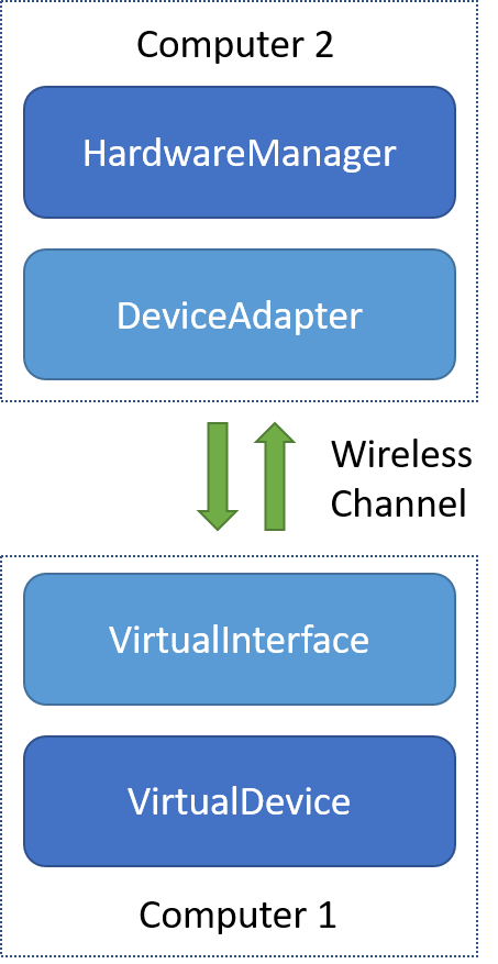
The stack that allows interacting with a Virtual IOTile Device from another computer as if it’s a real IOTile device over a communication channel like Bluetooth Low Energy.
Users rarely need to interact directly with a VirtualInterface object. Just as HardwareManager finds DeviceAdapters as needed and loads them by name, there is a script included with iotile-core called virtual_device that will take a VirtualDevice and provide access to it over a VirtualInterface.
Key Concepts
- DeviceAdapter
- A class whose job is to translate the abstract internal CoreTools representations of RPCs, Reports and Readings into concrete packets that can be sent to an IOTile Device connected via some communication mechanism. For example, the way an RPC is represented over the air will be different for a Bluetooth Low Energy connection than it would be for an HTTPS connection between the user and the IOTile Device. Device Adapters provide the translation layer between internal CoreTools objects and whatever needs to be sent/received over a communication channel. There needs to be one DeviceAdapter for each different communication mechanism that CoreTools supports.
- VirtualInterface
- VirtualInterfaces are python implementations of the communication stack inside an IOTile Device that allows it to communicate with CoreTools. For example, a Bluetooth Low Energy VirtualInterface would allow a Virtual Device to receive RPCs over Bluetooth LE using the Bluetooth stack built-in to your computer. The combination of a VirtualDevice and a VirtualInterface is a complete ‘software implementation’ of an IOTile Device.
- virtual_device
- A script included with the iotile-core package that loads in a VirtualDevice and VirtualInterface by name and then hosts the soft IOTile Device. This script simplifies the process of using VirtualInterfaces.
Using virtual_device
The virtual_device script is just a small program whose job is to let you run a VirtualDevice inside of a VirtualInterface without having to write custom python code.
VirtualInterfaces and VirtualDevices can be installed in your virtual environment by packages during the pip install process, and you can use virtual_device to list what installed interfaces and devices are available using the -l flag:
(iotile) > virtual_device -l
Installed Virtual Interfaces:
- awsiot
- bled112

Installed Virtual Devices:
- simple
- report_test
- realtime_test
- tracing_test
- no_app
In this case, we had the ability to serve virtual devices over AWS IOT’s MQTT broker and locally over bluetooth using a BLED112 USB->BLE dongle. There were 5 built-in virtual devices that we had available to us as well.
In this tutorial we’ll be using the realtime_test device that can be configured to produce realtime streaming data on demand.
Let’s see what the realtime_test device does.
-
class
iotile.mock.devices.RealtimeTestDevice(args)[source] Mock IOTileDevice that streams and traces data periodically
This device can be configured to stream data on any streams at any interval. It can be used for testing realtime streaming functionality of any other portion of the IOTile stack.
If no other arguments are passed, this device defaults to producing the value 100 on stream 0x1001 every second. If a streams dictionary is passed, that overrides this default setting.
You can also configure this device to broadcast readings without a connection on a periodic interval as well.
If no ‘trace’ argument is passed the device defaults to tracing the phrase ‘Hello trace world. ‘ every second. If a ‘trace’ array is passed, that overrides the default behavior.
Parameters: args (dict) – Any arguments that you want to pass to create this device. Supported args are:
- iotile_id (int): The UUID used for this device. If no UUID is
- specified, the default value of 1 is used.
- streams (dict): A map of strings with hex numbers to tuples of
- (interval, value) where interval is a float that expresses how often the stream should stream in seconds and value is an integer that is sent as the value every interval as a realtime reading (IndividualReadingReport). The stream id is the key of the streams dict which should be a string encoding of a hex number including the prefix 0x so that it can be parsed with int(key, 0).
- broadcast (dict): A map of strings with hex numbers to tuples
- of (interval, value) where interval is a float that
expresses how often the stream should stream in seconds
and value is an integer that is sent as the value every
interval as a broadcast reading (BroadcastReport). The
stream id is the key of the streams dict which should be a
string encoding of a hex number including the prefix 0x so
that it can be parsed with int(key, 0).
Note that a device can only broadcast a single value at once so if you specify multiple broadcast entries, only the last one to be triggered will be visible at any given time. For this reason, it is not useful to have multiple broadcast values with the same
intervalsince only one will ever be shown. - trace (list): A list of tuples which are (float, string) lists
- that will trace the fixed string every fixed interval given by the first float argument in seconds.
Basically, this is just a configurable device that can simulate realtime streaming data. Note that it takes a dictionary of parameters named args. When using the virtual_device script, you can set these parameters by passing a json config file using a –config flag on the command line.
Warning
For this next test to work, you will need two BLED112 USB Bluetooth dongles attached to your computer to allow for a loopback test and you will need to know either their device file on Mac OS and Linux or their COM port number on Windows.
In Linux, you will need to find the dongle existing in the /dev directory. You will also need to yourself to the sudo user group with sudo usermod -a -G dialout [username].
First, create a config file named device_config.json:
{
    "interface":
    {
        "port": "<path to device file or port, dongle 1>"
    },

    "device":
    {
        "iotile_id": "0x10",
        "streams":
        {
            "0x1000": [1.0, 50],
            "0x2000": [0.5, 100]
        }
    }
}
Now, start running your virtual device using:
(iotile) > virtual_device bled112 realtime_test --config device_config.json
Starting to serve virtual IOTile device
Note
If there was an error finding the VirtualDevice realtime_test, make sure you have a recent version of iotile-test installed using:
pip install --upgrade iotile-test
Note
To run a virtual device that hasn’t been installed, simply replace the installed device name with the path to your virtual device. For example, to run our “demo_streamer” device you might use:
(iotile) > virtual_device bled112 ./demo_streamer.py
Now your computer is advertising itself as an IOTile Device over bluetooth. Either using a second computer or using a different terminal on the same computer, we’re going to connect to the device over bluetooth:
(iotile) > iotile hw --port=bled112:<path to second dongle>
(HardwareManager) scan
{
    "connection_string": "88:6B:0F:18:34:AF",
    "expiration_time": "2017-05-18 10:36:23.491000",
    "low_voltage": false,
    "pending_data": false,
    "signal_strength": -39,
    "user_connected": false,
    "uuid": 16
}
Note how we used the port string bled112 to indicate that we wanted to connect to the device over bluetooth. In previous tutorials, we’ve used the virtual DeviceAdapter rather than Bluetooth Low Energy. Make sure you pass the correct COM port or file path in the port string otherwise you will get an error.
Now when we type scan, the results we get will be bluetooth based IOTile Devices that are in range of our computer. Here we see the virtual device that we just set up with UUID 0x10 (decimal 16). We see an RSSI signal strength of -39 dBm and see that no one is currently connected to it.
So, let’s connect and see the realtime streaming data come in over Bluetooth:
(HardwareManager) connect 0x10
(HardwareManager) enable_streaming
Now look back at the virtual device terminal and you’ll see it log audit messages telling you in detail what it’s doing:
Starting to serve virtual IOTile device
2017-05-18 10:42:40,453 [AUDIT ClientConnected] A client connected to this device
2017-05-18 10:42:40,865 [AUDIT RPCInterfaceOpened] A client opened the RPC interface on this device
2017-05-18 10:42:44,888 [AUDIT StreamingInterfaceOpened] A client opened the streaming interface on this device
2017-05-18 10:42:45,163 [AUDIT ReportStreamed] The device streamed a report to the client, report=IOTile Report of length 20 with 1 visible readings
2017-05-18 10:42:45,572 [AUDIT ReportStreamed] The device streamed a report to the client, report=IOTile Report of length 20 with 1 visible readings
2017-05-18 10:42:45,680 [AUDIT ReportStreamed] The device streamed a report to the client, report=IOTile Report of length 20 with 1 visible readings
2017-05-18 10:42:46,191 [AUDIT ReportStreamed] The device streamed a report to the client, report=IOTile Report of length 20 with 1 visible readings
2017-05-18 10:42:46,698 [AUDIT ReportStreamed] The device streamed a report to the client, report=IOTile Report of length 20 with 1 visible readings
2017-05-18 10:42:46,707 [AUDIT ReportStreamed] The device streamed a report to the client, report=IOTile Report of length 20 with 1 visible readings
2017-05-18 10:42:47,315 [AUDIT ReportStreamed] The device streamed a report to the client, report=IOTile Report of length 20 with 1 visible readings
2017-05-18 10:42:47,724 [AUDIT ReportStreamed] The device streamed a report to the client, report=IOTile Report of length 20 with 1 visible readings
2017-05-18 10:42:47,829 [AUDIT ReportStreamed] The device streamed a report to the client, report=IOTile Report of length 20 with 1 visible readings
2017-05-18 10:42:48,338 [AUDIT ReportStreamed] The device streamed a report to the client, report=IOTile Report of length 20 with 1 visible readings
2017-05-18 10:42:48,848 [AUDIT ReportStreamed] The device streamed a report to the client, report=IOTile Report of length 20 with 1 visible readings
2017-05-18 10:42:48,954 [AUDIT ReportStreamed] The device streamed a report to the client, report=IOTile Report of length 20 with 1 visible readings
2017-05-18 10:42:49,309 [AUDIT StreamingInterfaceClosed] A client closed the streaming interface on this device
2017-05-18 10:42:49,311 [AUDIT ClientDisconnected] A client disconnected from this device
These audit messages are a great way to see in detail what’s going on from the IOTile device’s standpoint if you’re trying to debug another part of the stack.
Now let’s see how RPCs look when sent over Bluetooth. Stop the virtual_device by sending it a Ctrl-C signal and then create a new one using the simple device that supports RPCs:
(iotile) > virtual_device bled112 simple --config device_config.json
Starting to serve virtual IOTile device
This device has a fixed UUID of 1, so let’s connect to it:
(iotile) > iotile hw --port=bled112:<path to second bled dongle
(HardwareManager) connect 1
(HardwareManager) controller
(SimpleProxy) tile_status
configured: True
debug_mode: False
app_running: True
trapped: False
The SimplyProxy is built-in to iotile-test for testing and demo purposes.
Let’s see what the RPCs look like over bluetooth now:
2017-05-18 10:53:48,516 [AUDIT ClientConnected] A client connected to this device
2017-05-18 10:53:48,854 [AUDIT RPCInterfaceOpened] A client opened the RPC interface on this device
2017-05-18 10:53:59,391 [AUDIT RPCReceived] An RPC has been processed (id=4, address=8, payload=""), status=192, response="ffff53696d706c6501000003"
2017-05-18 10:53:59,440 [AUDIT RPCReceived] An RPC has been processed (id=4, address=8, payload=""), status=192, response="ffff53696d706c6501000003"
2017-05-18 10:54:03,661 [AUDIT RPCReceived] An RPC has been processed (id=4, address=8, payload=""), status=192, response="ffff53696d706c6501000003"
Here we see the RPC as received by the virtual device from the bluetooth stack and the raw hex bytes sent back in response. Note that when we called controller on the HardwareManager instance it sent two RPCs on our behalf to ask the virtual device for its 6-byte identifier that it uses to match it to a Proxy object. That’s how it knew that it should load the SimpleProxy object.
The tile_status command is supported by every IOTile Device (and even by each individual tile inside composite devices) and just shows basic status information about whether there are any issues with the device. In this case everything’s running fine.
Scripting Actual Devices
One of the core principles of IOTile is orthogonality, which means that a given script or command should be able to be used no matter what the IOTile Device is and no matter how its connected to the user. In this case, we’re going to reuse the exact same script we used before to print realtime streaming data from our virtual device to now print the realtime data coming from our actual (soft) device over bluetooth.
Start the realtime_test device again:
(iotile) > virtual_device bled112 realtime_test --config device_config.json
Starting to serve virtual IOTile device
Now load up your realtime stream dumping script from the last tutorial (fixing the port to use bled112 instead of virtual (test_script.py):
from iotile.core.hw.hwmanager import HardwareManager
from iotile.core.hw.reports import IndividualReadingReport, IOTileReading

with HardwareManager(port='bled112:<path to dongle or COM port>') as hw:
    hw.connect(0x10)
    hw.enable_streaming()

    # hw.iter_reports() will run forever until we kill the program
    # with a control-c so make sure to catch that and cleanly exit
    # without printing an exception stacktrace.
    try:
        for report in hw.iter_reports(blocking=True):

            # Verify that the device is sending realtime data as we expect
            assert isinstance(report, IndividualReadingReport)
            assert len(report.visible_readings) == 1

            reading = report.visible_readings[0]
            assert isinstance(reading, IOTileReading)

            print("Received {}".format(reading))
    except KeyboardInterrupt:
        pass
Run it and see the realtime data coming from your device:
(iotile) > python ./test_script.py
Received Stream 4096: 50 at 2017-05-18 18:05:45.693000
Received Stream 8192: 100 at 2017-05-18 18:05:45.693000
Received Stream 8192: 100 at 2017-05-18 18:05:46.211000
Received Stream 4096: 50 at 2017-05-18 18:05:46.727000
Received Stream 8192: 100 at 2017-05-18 18:05:46.727000
Received Stream 8192: 100 at 2017-05-18 18:05:47.337000
Received Stream 4096: 50 at 2017-05-18 18:05:47.842000
Received Stream 8192: 100 at 2017-05-18 18:05:47.852000
Received Stream 8192: 100 at 2017-05-18 18:05:48.350000
Received Stream 4096: 50 at 2017-05-18 18:05:48.859000
Received Stream 8192: 100 at 2017-05-18 18:05:48.859000
Received Stream 8192: 100 at 2017-05-18 18:05:49.468000
If you have a physical IOTile device as well, you could now point your script at it and have it show you the realtime sensor data coming from the device.
Next Steps
After finishing this tutorial, you’re ready to build your own virtual IOTile Device and allow access to it over bluetooth.
Setting Up a Gateway
You may have to pip install iotile-gateway.
Many times individual IOTile Devices are not able to directly connect to the internet and instead talk exclusively to an intermediate gateway device. This is usually because the devices lack the required communications hardware to send multi-hop or IP routed transmissions. An example would be a battery powered wireless sensor connected via Bluetooth Low Energy. BLE devices connect to a local central device in a point-to-point fashion without a built-in provision for connecting to the internet.
So, there’s often a need for a gateway that knows how to connect to a specific sensor device and then serves access to that device over a different protocol, acting as a translator between, e.g. BLE and Websockets, or BLE and MQTT.
Since all IOTile Devices implement the same basic interfaces for streaming data and receiving RPC commands, we can make a generic gateway program that translates requests from any supported protocol into any other supported protocol.
This program, and the python objects behind it, is called iotile-gateway and is provided by the iotile-gateway package in CoreTools.
Goals
- Understand how to configure iotile-gateway to translate between communication protocols.
- Use iotile-gateway to aggregate devices across multiple communication protocols by plugging multiple DeviceAdapters into the same gateway.
- Understand the use case for mixing physical and virtual IOTile devices in the same gateway to allow for remote configuration of the gateway computer as well as providing access to other IOTile Devices.
Background
In previous tutorials, we’ve seen how DeviceAdapters provide a generic way to allow access to IOTile devices from multiple clients and how HardwareManager allows a single client or script to discover and make a connection to a specific IOTile Device.
We’ve also seen how we can create our own device and serve access to it using a VirtualInterface. In this tutorial we’re going to introduce GatewayAgents.
GatewayAgents are the direct complement to DeviceAdapters. Whereas DeviceAdapters standardize devices that may have very different communication protocols, GatewayAgents take those standardize devices and re-broadcast them over a different communucation protocol. So, you could take a device connected over Bluetooth and serve it up over Websockets, MQTT, or HTTPS.
Since there are many moving pieces in performing this kind of translation, there needs to be a host application that provides the framework for linking DeviceAdapters and GatewayAgents together. This program is called iotile-gateway and is installed as a script when you pip install the iotile-gateway package in CoreTools.
The heavy lifting is done by an asynchronous event loop managed by the AggregatingDeviceAdapter class.
-
class
iotilegateway.device.AggregatingDeviceAdapter(port=None, adapters=None, loop=<iotile.core.utilities.async_tools.event_loop.BackgroundEventLoop object>)[source] Aggregates multiple device adapters together.
This class aggregate all of the available devices across each DeviceAdapter that is added to it and route connections to the appropriate adapter as connections are requested. An API is provided to make connections to devices, monitor events that happen on devices and remember what devices have been seen on different adapters.
It is assumed that devices have unique identifiers so if the same device is seen by multiple DeviceAdapters, those different instances are unified and the best route to the device is chosen when a user tries to connect to it. For this purpose there is an abstract notion of ‘signal_strength’ that is reported by each DeviceAdapter and used to rank which one has a better route to a given device.
Parameters: loop (BackgroundEventLoop) – The background event loop that we should use to run our adapters. Defaults to SharedLoop.
By itself, AggregatingDeviceAdapter does not allow serving access to IOTile Devices, it just aggregates multiple DeviceAdapters together and unifies the view of the devices that they can see.
There still needs to be a way to configure what DeviceAdapters to add to the AggregatingDeviceAdapter and to specify what GatewayAgents should be included as well.
This is performed by the IOTileGateway class. IOTileGateway is designed for simple integration into host applications and forms the backbone of the iotile-gateway command line program.
-
class
iotilegateway.gateway.IOTileGateway(config, loop=<iotile.core.utilities.async_tools.event_loop.BackgroundEventLoop object>)[source] A gateway that finds IOTile devices using device adapters and serves them using device servers.
The gateway runs in separate thread inside of a BackgroundEventLoop and you can call the synchronous wait function to wait for it to quit. It will loop forever unless you stop it by calling the stop() or stop_from_signal() methods.
IOTileGateway should be thought of as a turn-key gateway object that translates requests for IOTile Device access received from one or more AbstractDeviceServer into commands sent to one or more AbstractDeviceAdapters. It is a multi-device, multi-user, multi-protocol system that can have many connections in flight at the same time, limited only by the available resources on the computer that hosts it.
The arguments dictionary to IOTileGateway class has the same format as the json parameters passed to the iotile-gateway script that is just a thin wrapper around this class.
Parameters: config (dict) – The configuration of the gateway. There should be two keys set:
- servers (list):
- a list of dictionaries with the name of the device server and any arguments that should be passed to create it.
- adapters (list):
- a list of dictionaries with the device adapters to add into the gateway and any arguments that should be use to create each one.
The overall structure of the iotile-gateway system is shown in the figure below. You can see the different device adapters that can be used to find IOTile Devices and the various gateway agents that allow users to access them.
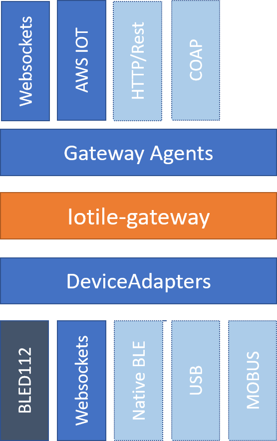
The structure of the iotile-gateway program that translates between different communication protocols to allow remote control of IOTile Devices that don’t possess long-range communications hardware.
Key Concepts
A class that takes multiple DeviceAdapters and merges all of the devices that they can see. Requests to connect to individual devices are routed to the appropriate DeviceAdapter based on which adapters can see that device, what their signal strength is and whether they have the resources for an additional connection.
- IOTileGateway
- A helper class that locates and loads DeviceAdapter and GatewayAgent plugins and then runs a DeviceManager instance with those plugins in a separate thread to allow for easy integration into a host application
- GatewayAgent
- A class that serves access to IOTile Devices over a communication protocol. This class serves the opposite function as a DeviceAdapter and you would imagine a natural pairing where each DeviceAdapter has a corresponding GatewayAgent.
- iotile-gateway
- A cross-platform command line script that allows turning a computer into a turn-key gateway that searches for IOTile Devices using DeviceAdapters and then serves access to them using GatewayAgents. A JSON configuration file lets you specify what plugins to load and how to configure them
Using iotile-gateway
The iotile-gateway program is fairly turn-key. You just need to tell it what DeviceAdapters to load and what GatewayAgents to use. The DeviceAdapters are configured by passing the same ‘port’ string you would use in the iotile tool.
The GatewayAgents have more configurability and take a dictionary of arguments that are specific to each agent. In this example, we’re going to use our venerable VirtualDeviceAdapter to connect to a virtual device and serve access to it over Websockets.
Websockets are a bidirectional communication channel built on top of http that is widely used in javascript web applications, so serving IOTile Devices over web sockets is a great way to connect them to web apps.
We’ll need to create a config file with the required information (named gateway.json):
{
    "agents":
    [
        {
            "name": "websockets",
            "args":
            {
                "port": 5120
            }
        }
    ],

    "adapters":
    [
        {
            "name": "virtual",
            "port": "realtime_test"
        }
    ]
}
Then we just run iotile-gateway and point it to our config file:
(iotile) > iotile-gateway --config=gateway.json
I-2017-05-19 14:38:18,977-gateway   :94   Loading agent by name 'websockets'
I-2017-05-19 14:38:19,381-ws_agent  :38   Starting Websocket Agent on port 5120
I-2017-05-19 14:38:19,388-gateway   :116  Loading device adapter by name 'virtual' and port 'realtime_test'
Now (in another shell or a separate computer on the same network), we can connect to the gateway just like we connect directly to an IOTile Device by specifying a protocol supported by one of the gateway’s agents, in this case websockets:
(iotile) > iotile hw --port=ws:localhost:5120/iotile/v1
(HardwareManager) scan
{
    "adapters": [
        [
            0,
            100,
            "0/1"
        ]
    ],
    "best_adapter": 0,
    "expires": "2017-05-26 13:23:46.277000",
    "signal_strength": 100,
    "uuid": 1
}
Note how there is a little more detail here than when you scan directly from the IOTile tool. In particular we see a list of all of the DeviceAdapters that could see the device ranked in order of signal strength and a key specifying the best adapter to use to connect to the device.
If this were, for example, a Bluetooth device and we had two different Bluetooth adapters connected to the computer, we would see the device twice but they would both be merged into a single entry with the closest adapter used to actually make the connection.
Combining Multiple Device Adapters
There is no restriction on the number of different device adapters that you can connect to a gateway, so let’s use two virtual adapters:
{
    "agents":
    [
        {
            "name": "websockets",
            "args":
            {
                "port": 5120
            }
        }
    ],

    "adapters":
    [
        {
            "name": "virtual",
            "port": "realtime_test"
        },

        {
            "name": "bled112"
        }
    ]
}
Important
You need a BLED112 USB bluetooth dongle plugged into your computer for this to work.
In this case, we’re going to find physical IOTile Devices over bluetooth as well as our virtual device. This combination of physical and virtual devices is often very useful since virtual devices can provide you a way to configure things on the computer running the gateway program.
For example, lets say you’re deploying a gateway on a remote farm that you are going to use to control a variety of bluetooth sensors. It would be great if you could also control the gateway computer itself. By making a virtual device that allows control of the gateway and connecting it to the iotile-gateway as well as the bluetooth adapter, you’re able to introspectively access the gateway just as easily as you can reach through it to access a local bluetooth device:
(iotile) > iotile hw --port=ws:localhost:5120/iotile/v1
(HardwareManager) scan
{
    "adapters": [
        [
            0,
            100,
            "0/1"
        ]
    ],
    "best_adapter": 0,
    "expires": "2017-05-26 13:39:15.516000",
    "signal_strength": 100,
    "uuid": 1
}
{
    "adapters": [
        [
            1,
            -79,
            "1/C0:05:C8:DB:E5:45"
        ]
    ],
    "best_adapter": 1,
    "expires": "2017-05-19 15:00:16.032000",
    "low_voltage": false,
    "pending_data": true,
    "signal_strength": -79,
    "user_connected": false,
    "uuid": 53
}
{
    "adapters": [
        [
            1,
            -66,
            "1/D0:45:A7:7E:A9:F0"
        ]
    ],
    "best_adapter": 1,
    "expires": "2017-05-19 15:00:16.283000",
    "low_voltage": false,
    "pending_data": false,
    "signal_strength": -66,
    "user_connected": true,
    "uuid": 54
}
Here we see a number of devices that our gateway found over bluetooth as well as our virtual device. You can connect to any device by uuid in the same manner so you don’t have to worry about which devices are physical vs virtual.
Next Steps
After this tutorial you should be ready to set up your own IOTile Gateway that translates devices from one communication protocol to another. You should also be able to use what you learned in the previous tutorials to add virtual devices to your gateway that let you control things directly connected to the gateway computer or configure the gateway itself as if it were an IOTile Adapter.
You can read on to figure out how to configure your own physical IOTile devices using the SensorGraph language.
Introduction to SensorGraph
Previous tutorials have covered how to create virtual IOTile devices that expose functionality in terms of RPCs that can be called to, for example, read a sensor or flip a switch. We’ve also seen how we can interact with those devices from a computer using CoreTools to send commands and extract data over a variety of communications channels.
However, we haven’t yet touched on how you could embed a program into one of these devices so that it can be left running and autonomously collect data or take actions.
For example, lets say you have a device that can measure the temperature of the air in the room and you want to configure it to measure that temperature every 10 minutes and if its too hot, turn on the AC.
Basically you want a simple script that does the following:
every 10 minutes
{
    measure temperature
}

if temperature > upper_limit
{
    enable AC
}
In this tutorial we are going to cover how to write these scripts for an IOTile device in a language called SensorGraph that makes it easy to write scripts and verify that they work as intended before deploying them to a potentially remote and mission critical location.
Goals
- Understand what SensorGraph is at a high level and what the major components of the sensor graph system are.
- Be able to write and simulate SensorGraph scripts on your computer using the iotile-sensorgraph package in CoreTools.
- Understand the major statements and blocks that make up a SensorGraph script.
Background
The way to think of an IOTile device is as a set of APIs, just like a web service would have a set of REST APIs that you can wire together to make an application.
Without an Application tying the APIs together the system won’t do anything, it will just sit and wait for someone to call one of its APIs (like we did in previous tutorials).
Most applications that we want to write on IOTile devices are fairly small and just wire together a few APIs to collect data and then prepare it for either remote transmission to the cloud or use it to control some local process.
There are three parts to an IOTile application:
Configuring the device: An IOTile device is made up of several different modules called tiles. These tiles are designed to be used in a variety of different ways, so you may need to configure them to be in the right mode of operation for what you want. Configuration of all tiles happens once when the IOTile device turns on.
Wiring tiles together to collect data: Once the IOTile device is configured, there needs to be a script that it runs through that tells it what RPCs to call on which tiles in order to collect data or control things. This script could either be time driven like ‘collect data every 10 minutes’ or event driven as in ‘when this happens to this’. Combinations of time driven and event driven actions are also possible.
Choosing what data to report: Often times IOTile devices are designed to send data they collect to a remote server in the cloud for further processing. Usually you only want a subset of the data that an IOTile device generates to be sent remotely in order to save bandwidth, power or money. So, there needs to be some rules in place that select what data gets sent remotely.
The selected data is packaged into Reports as described in a previous tutorial. In this section we’re talking about how the device knows what data should go into those reports and what data is only for internal use.
The part of the IOTile device that is responsible for choosing data for remote transmission is a Streamer. Streamers determine what data is sent, under what conditions it is sent, how retries are handled and what report format to use (i.e. what level of security and robustness guarantees are required).
Normally, the data that an IOTile device generates can be divided into two classes:
- Realtime Data: Realtime data is continually being regenerated and does not have any long term value. It could be, for example, the current temperature of a device that is updated once per second. There is no need to keep more than one current temperature reading around.
- Historical Data: Other data is specifically designed to be saved in long term storage. For example, consider using that same temperature monitoring device to record a profile of the temperature experienced by a package along a multi day journey around the world. You want to keep historical readings around because the point is to have a record, not just the latest value.
Because these two types of data are so common, IOTile Devices handle them separately. Realtime data is referred to as unbuffered data and is never stored in a persistent memory location like flash memory. It can change very rapidly without wearing out any persistent storage medium.
In contrast, historical data is treated as buffered data and every value written to a data stream marked as historical data will be saved securely and assigned a globally unique identifier so that it can be robustly transferred to a remote server and acknowledged that it was correctly received.
So, buffered data corresponds to data that should be tracked over time and unbuffered is for realtime data and intermediate results that will be overwritten when new data comes in.
Only the user knows what data should be buffered vs unbuffered so part of designing a SensorGraph is specifying how to treat each data stream that is generated.
Key Concepts
- Tile Configuration
- A series of variable assignments that are performed on an IOTile module in order to prepare it for operation. These configurations can do things like set what units it reports data in or selecting what sensor is plugged into a tile that can work with many different kinds of sensors.
- Streamer
- A task running on an IOTile Device whose job is to send some subset of the data generated by that device to a remote server in a configurable way. Streamers choose what data to send, when to send it, how it is packaged and how retries are handled if an initial attempt to send the data fails.
- Buffered Data
- Data that is tracked with a unique identifier and stored securely in long term storage. Once buffered data is generated, it will stay around until the device is forced to overwrite it due to a lack of space or it is successfully transferred to a remote server.
- Unbuffered Data
- Data that is ephemeral and not persistently stored. Whenever a new reading comes in, it overwrites that last unbuffered reading in the same data stream.
Creating Your First SensorGraph
With this background information in hand, we’re ready to try out our first complete sensor graph in a simulator so we can see how everything works.
Important
For this tutorial you will need to make sure the iotile-sensorgraph package is installed:
pip install -U iotile-sensorgraph
In this tutorial, we’re going to write sensor graphs by example without diving too much into the mechanics behind it. A later tutorial will go deeper into how everything works behind the scenes.
Let’s start with a complete simple sensor graph that just calls an RPC every 10 minutes:
every 10 minutes
{
    call 0x8000 on slot 1 => output 1;
}
Basically we’re asking the device to call the RPC with id 0x8000 on the tile located in slot 1 once every 10 minutes and to store the output in a stream named output 1. Save this file as simple.sgf and then you can simulate it in the sensor graph simulator named iotile-sgrun that is installed by the iotile-sensorgraph package:
(iotile) > iotile-sgrun simple.sgf -s 'run_time 1 hour' -w 'output 1'
(     600 s) output 1: 0
(    1200 s) output 1: 0
(    1800 s) output 1: 0
(    2400 s) output 1: 0
(    3000 s) output 1: 0
(    3600 s) output 1: 0
In addition to the sensor graph file that we wanted to simulate, we also passed a stop condition (-s ‘run_time 1 hour’) that stops the simulation after 1 hour of simulated time has passed. We also told the simulator to watch (-w) the stream named ‘output 1’ and report whenever data was written to it.
The output showed us that a 0 was output ever 10 minutes (600 seconds) for a total of 6 readings in 1 hour.
This is a complete sensor graph that you could program into an iotile device and have it take data every 10 minutes forever. It’s not that interesting of a SensorGraph though, so we’ll add some more to it later.
Mocking RPCs
In our example above, the simulator called the RPC numbered 0x8000 and stored its result in output 1. Evidently the RPC returned a 0.
By default, all simulated RPCs return 0.
You can override this behavior by specifying an explicit return value using the -m option to the simulation. Let’s say we want to simulate an RPC that returns 15 rather than 0:
(iotile) > iotile-sgrun simple.sgf -s 'run_time 1 hour' -w 'output 1' -m 'slot 1:0x8000 = 15'
(     600 s) output 1: 15
(    1200 s) output 1: 15
(    1800 s) output 1: 15
(    2400 s) output 1: 15
(    3000 s) output 1: 15
(    3600 s) output 1: 15
Note
There is a more advanced way to use the simulator called ‘semihosting’ where the RPCs are sent to an actual iotile device to run and the response is returned to the simulator. This lets you test your sensor graph as if it were running on an actual device while still being able to watch any stream and accelerate the passage of simulated time to verify that the sensor graph behaves as you would expect over time without having to have an actual device running for that long.
How to use semihosting will be covered in the next tutorial.
The syntax for mocking an RPC is straightforward:
-m "<slot id>:<rpc number> = <value>"

- <slot id> should be either the literal value controller or 'slot X'
where X is a number >= 1.

- <rpc number> should be the same 16 bit number in either decimal or hex
that you enter into the sensor graph to identify the RPC you want to call.

- <value> should be an integer that will simulate what the RPC returned.
It is not currently possible to change what the mocked RPC returns over
time from the command line; it always returns the same thing.

For example:

- m "controller:0x2000 = 0x50"
- m "slot 5:1500 = 12"
Adding Control to a SensorGraph
The first sensor graph above just got data via an RPC and then saved it as a buffered output. We used an every <time> block to specify how often we wanted the RPC called. Now we’re going to introduce the on block that lets us inspect and act on the values we get.
Let’s say our RPC represents temperature and we want to turn on the AC when the temperature rises above a certain temperature (say 80 degrees). We can express that as follows:
every 10 minutes
{
    call 0x8000 on slot 1 => unbuffered 1;
}

on value(unbuffered 1) > 80
{
    # In this example, 0x9000 is the RPC that turns on the AC
    call 0x9000 on slot 2;
}

on unbuffered 1
{
    copy => output 2;
}
This sensor graph will still log the temperature every 10 minutes but also check if its value is greater than 80 degrees and call another RPC that turns on the AC. (Note in a real life example, you would probably want another on block to turn off the AC as well!)
Note
See how there are two ways to use the call statement. In the first call, we specified that we wanted to keep track of the value returned by the RPC so we gave it a name. In the second call, we didn’t care about the return value of the RPC so we didn’t give it an explicit name.
Internally, the sensor graph compiler automatically allocated an unused stream for this value and we’ll see in the next tutorial how this turns into the actual rules that could be programmed.
Adding Realtime Data Outputs
Most IOTile devices don’t have screens. However, users can walk up to them with their phones and access their virtual screen over Bluetooth Low Energy.
When a user is standing next to an IOTile device, they probably don’t want to wait 10 minutes to see the next data point, so there needs to be a way to trigger faster data outputs when a user is connected to the device.
This functionality is builtin to sensor graph and can be enabled using a when block as in the example below:
every 10 minutes
{
    call 0x8000 on slot 1 => unbuffered 1;
}

when connected to controller
{
    on connect
    {

    }

    every 1 second
    {
        call 0x8000 on slot 1 => unbuffered 10;
        call 0x8001 on slot 1 => unbuffered 11;
    }

    on disconnect
    {

    }
}
The when connected to controller block specifies actions that should only be taken when a user is connected. The on connect and on disconnect blocks are not required if they are unused but are included here for reference.
This sensor graph says that when a user is connected two RPCs should be made every second and the results stored in unbuffered streams 10 and 11.
The on connect and on disconnect blocks allow you to do any required setup or cleanup on the device that might be necessary to prepare it for high resolution outputs and then put it back into low power autonomous mode when the user disconnects.
Now let’s simulate this for 10 seconds:
(iotile) > iotile-sgrun simple.sgf -s 'run_time 10 seconds' -w "unbuffered 10" -w "unbuffered 1"
(iotile) >
We didn’t see any output because no user was connected and we didn’t wait 10 minutes for a reading.
So let’s wait 10 minutes to make sure the readings are happening:
(iotile) > iotile-sgrun simple.sgf -s 'run_time 10 minutes' -w "unbuffered 10" -w "unbuffered 1"
(     600 s) unbuffered 1: 0
Now let’s simulate a connected user with the -c flag:
(iotile) > iotile-sgrun simple.sgf -s 'run_time 10 seconds' -w "unbuffered 10" -c

(       1 s) unbuffered 10: 0
(       2 s) unbuffered 10: 0
(       3 s) unbuffered 10: 0
(       4 s) unbuffered 10: 0
(       5 s) unbuffered 10: 0
(       6 s) unbuffered 10: 0
(       7 s) unbuffered 10: 0
(       8 s) unbuffered 10: 0
(       9 s) unbuffered 10: 0
(      10 s) unbuffered 10: 0
Notice how we now got realtime outputs now in the stream unbuffered 10 every second.
Selecting Data to Stream
In the beginning of this tutorial, we laid out three jobs for a SensorGraph:
- Configuring tiles
- Wiring together RPCs into an application
- Selecting data to send remotely
We’ve focused on step 2 so far. Step 1 will be addressed in the next tutorial so we will briefly touch on step 3 now.
As mentioned, the way to send data from an IOTile Device is referred to as Streaming and is done by a Streamer.
When you write a sensor graph you need to explicitly say what streamers you want to set up so that the device can be configured properly. Just like there are two kinds of data produced by an IOTile device, there are also two kinds of streamers: realtime and historical.
Realtime streamers report the latest value in a stream without worrying about robustness, packaging it, or retrying the transmission if its not successful because it’s expected that they can just send an updated value when its available.
Historical (or Robust) streamers take much more care in signing and optionally encrypting the data before sending it and keeping track of exactly which readings have been acknowledged as successfully received by the cloud so that no data can be lost. Historical data is resent until it is successfully received.
The syntax for specifying streamers is straightforward. You just specify what data streams you want to send and whether you want to send them as realtime or historical data:
[manual] (signed | realtime) streamer on <selector>;
The manual keyword will be covered in the next tutorial but it gives the user more flexibility in when the streamer tries to send data. By default streamers are “automatic”, which means they try to send data whenever it is available.
You choose whether data is realtime or historical by specifying the keywords realtime or signed and finally you choose what data to send by specify a Stream Selector. This can be just the name of a stream or it can be a wildcard like all outputs.
Here are a few examples:
manual signed streamer on all outputs;
realtime streamer on unbuffered 10;
These two streamers say that we would like to report realtime data whenever it is available on the unbuffered 10 stream and we would also like to send all output streams as historical data that will be triggered manually.
In the next tutorial, we will cover how to trigger manual streamers from a sensor graph.
Next Steps
Read about how to write more advanced sensor graphs as well as how to program or test them with actual devices.
Deploying Sensor Graphs
In the last tutorial we covered the basics of how to make your own SensorGraph. Now we are going to talk about how to program that sensor graph into an IOTile device and how to “semihost” it so that you can test out the RPCs without needing to fully program it into the device.
Goals
- Be able to semihost a sensor graph to test RPCs on an actual device
- Be able to program a sensor graph onto a device for autonomous operation
Background
There are two big parts to a sensor graph. The first is the actual graph that is coordinating what RPCs to call in order to acquire data or control something. The second is the underlying hardware that implements those RPCs.
Semihosting is running the sensor graph on your computer but delegating the RPCs to an actual hardware device. This is useful because:
- It means you can accelerate the passage of time to uncover subtle bugs that only manifest over a long period of operation.
- It means you have access to all of the watch infrastructure of the simulator to see in detail what is happening in each stream. This is more difficult once the sensor graph is actually embedded fully into a physical device.
Key Concepts
Semihosting
Running a sensor graph on your computer while dispatching the RPCs to be run on an actual device. This device is connected to using the same HardwareManager based methods as the previous tutorials, so the device can be anywhere in the world or even virtual.
Semihosting a Sensor Graph
Note
In order to run the following commands successfully, make sure that you have the iotile-test package installed in order to have the right test virtual device:
pip install -U iotile-test
Semihosting a sensor graph is really easy. You just need to know two things:
- the port string for the DeviceAdapter that you want to use to connect to your IOTile device. This is the same string that you use with the iotile tool (i.e. the port string in iotile hw –port=<port string>).
- the device id of the device that you want to connect to (like 0xABCD)
Simply pass the port as a -p argument to iotile-sgrun and the device id in a -d parameter and then simulate the sensor graph as normal. The simulator will connect to the device using the supplied information and run all RPCs on the device.
For example, save the following sensor graph as test.sgf:
every 10 seconds
{
        call 0x8000 on controller => unbuffered 2;
        call 0x8002 on controller => unbuffered 2;
}

on value(unbuffered 2) == 5
{
        call 0x8001 on slot 1 => output 1;
}
We’re going to semihost using a virtual device in iotile-test called (appropriately) sg_test. The sg_test device just has two RPCs that are useful for learning sensor graphs:
controller: 0x8000 returns a random number between 0 and 100
slot 1: 0x8001 returns the fixed integer 42
Let’s try it out:
(iotile) > iotile-sgrun test.sgf -p virtual:sg_test -d 1 -s 'run_time 1 minute' -w 'unbuffered 2'
(      10 s) unbuffered 2: 80
(      20 s) unbuffered 2: 59
(      30 s) unbuffered 2: 25
(      40 s) unbuffered 2: 45
(      50 s) unbuffered 2: 24
(      60 s) unbuffered 2: 1
We can also run for along time to see the random value trigger our second sensor graph rule on unbuffered 2 == 5:
(iotile) > iotile-sgrun test.sgf -p virtual:sg_test -d 1 -s 'run_time 1 hour' -w 'output 1'
(     490 s) output 1: 42
(     530 s) output 1: 42
(     610 s) output 1: 42
(    1290 s) output 1: 42
(    1810 s) output 1: 42
(    2360 s) output 1: 42
(    2870 s) output 1: 42
Note the random timestamps since those were the random times that RPC 0x8000 on the controller returned 5. Your results should vary.
Important
You can still mock RPCs and those will override RPCs defined in the semihosting device. This can be useful for injecting unlikely conditions into more complicated sensor graphs for testing.
Let’s mock RPC 0x8001 on slot 1 to return 50 rather than 42:
(iotile) > iotile-sgrun test.sgf -p virtual:sg_test -d 1 -s 'run_time 1 hour' -w 'output 1' -m "slot 1:0x8001 = 50"
(      40 s) output 1: 50
(     390 s) output 1: 50
(    2260 s) output 1: 50
(    2760 s) output 1: 50
(    3250 s) output 1: 50
(    3360 s) output 1: 50
Programming Into a Device
Note
Before programming a sensor graph to a device, your environment will need its appropriate support package. In this example, we will need the proxy image for the nrf52832:
pip install iotile-support-con-nrf52832-3
Currently the best way to program a sensor graph into an actual device is to use a combination of the iotile-sgcompile and iotile tools. Given your sensor graph, compile it with an output format of snippet. This produces a list of commands that can be entered into the iotile tool to program the sensor graph onto a device. You can just pipe this to the iotile tool to program the sensor graph.
For example, let’s look at the snippet corresponding to the test.sgf that we created above:
(iotile) > iotile-sgcompile test.sgf -f snippet
disable
clear
reset
add_node "(system input 2 always) => counter 1024 using copy_all_a"
add_node "(system input 3 always) => counter 1025 using copy_all_a"
add_node "(counter 1024 when count >= 1) => counter 1026 using copy_latest_a"
add_node "(counter 1026 when count == 1 && constant 1024 always) => unbuffered 2 using call_rpc"
add_node "(counter 1026 when count == 1 && constant 1025 always) => unbuffered 2 using call_rpc"
add_node "(unbuffered 2 when value == 5) => unbuffered 1024 using copy_latest_a"
add_node "(unbuffered 1024 when count == 1 && constant 1026 always) => output 1 using call_rpc"
set_constant 'constant 1024' 557056
set_constant 'constant 1025' 557058
set_constant 'constant 1026' 753665
persist
back
config_database
clear_variables
set_variable 'controller' 8192 uint32_t 1
back
reset
You can see how these are just iotile tool commands. They are meant to be entered in the controller sensor_graph context in the iotile tool while connected to an IOTile device.
So the easiest way to program this into a device is:
(iotile) > iotile-sgcompile test.sgf -f snippet | iotile hw --port=<port> connect <device id> controller sensor_graph
When the command terminates the new sensor graph will be programed into the device and the device will have reset itself to start running the sensor graph.
Simulating in Realtime
If you want to simulate your sensor-graph in real time, i.e. waiting 10 minutes for an every 10 minutes block to fire, you can do so by passing the -r flag to the simulator.
Next Steps
You can cover more advanced sensor graph concepts in the next tutorial or start writing and testing your own sensor graphs!
The SensorGraph Language
In this tutorial we’re going to cover the main statements that you can write in a sensor graph and what they do.
Goals
- Understand the key statements and blocks that make up the sensor graph language.
Background
Like most languages, there are two kinds of elements in a sensor graph: Blocks and Statements.
Blocks are containers for statements that are used to influence how the statements are compiled. All blocks consist of a single line that starts the block and then zero or more statements contained in curly braces.
Statements are the actual commands that you want your IOTile device to run. An empty block should have no effect. All statements are a single line and end with a semicolon.
Whitespace is ignored and comments may be included anywhere by prefacing a line with the # character. There are no C-like multiline comments.
Call Statements
The most basic statement in a sensor graph is the call statement that calls an RPC on a tile. It’s syntax is:
call <rpc id> on <slot id> [=> <output stream>];
Important
The way to interpret a syntax definition like the one above is as follows:
- Anything in < > characters should be substituted in an actual command with a specific value. It is just a placeholder.
- Any word or token not enclosed in < > characters must be literally included as part of the statement. So, the keyword ‘call’ is required to start a call statement.
- Anything in a [ ] is optional.
This statement calls an RPC and optionally stores the result in <output stream>. It must be used inside of a block that allows triggering statements like an on block or every block.
- <rpc id> should be a number.
- <slot id> should be a Slot Identifier.
- <output stream> should be Data Stream.
Copy Statements
Copy statements copy a value from an input stream to an output stream:
copy [all | count] [<input stream>] => <output stream>;
There are three ways you can copy things:
- copy all copies all readings that have not been processed yet from the input to the output stream.
- copy just copies the latest reading, ignoring any readings that may have been pushed before this statement triggered.
- copy count copies the number of readings currently in the input stream to the output stream.
If an explicit input stream is given, the data is copied from that stream, otherwise there is always an implicit trigger stream defined in every block.
Implicit streams are useful inside on blocks since the copy command would then work with the stream data that triggered the on condition.
Trigger Statements
Trigger statements trigger the streaming of data inside manual streamers. Their usage is:
trigger streamer <index>;
where <index> is the index of the streamer you want to trigger, i.e. the first streamer defined is index 0, the second is index 1, etc. Trigger statements are used to trigger manual streamer that don’t try to automatically send data whenever it is available.
Streamer Statements
You define a streamer with a streamer statement:
[manual] [realtime] streamer on <stream selector> [with streamer <index>];
If you specify a with clause, this streamer will trigger whenever the other streamer identifier by index triggers.
You can specify either realtime or historical streamers by specifying realtime or nothing.
The Every Block
Every blocks run the commands inside of them every given time interval. The syntax is:
every <time interval>
{
    <statement 1>;
    ...
    <statement N>;
}
Each statement (1 through N) will be called exactly once in order every time interval.
- <time interval> should be a TimeInterval.
The On Block
On blocks run statements when a specific event happens. They are like if statements in other languages. There are three possible triggers for an on block:
on value(<stream>) <op> <reference>
{
    <statements>...
}

on count(<stream>) <op> <reference>
{
    <statements>...
}

on <named event>
{
    <statements>...
}
The first on block triggers when a comparison between the value in a stream and a constant reference value is true.
The second on block triggers when a comparison betwen the number of readings in a stream and a constant reference value is true.
The third on block triggers when the specific named event happens. Currently the major named events are connect and disconnect which are defined only inside of a when connected block.
The possible comparison operations are: <, <=, ==, >, >=.
You cannot nest another block inside of an on block.
The When Block
When blocks let you conditionally trigger statements to happen only when a user is connected to a device. They can contain on blocks and every blocks, which can in turn contain statements:
when connected to <slot id>
{
    on connect
    {
        <statements>
    }

    every <time interval>
    {
        <statements>
    }

    on disconnect
    {
        <statements>
    }
}
The <slot id> is the tile that the user is connected to, in case there are multiple communications tiles in a device. This is almost always controller.
Statements inside the on connect block will run once when the user connects and statements in on disconnect will run once when the user disconnects.
Statement inside an every block nested inside a when block will run every time interval while a user is connected.
The Config Block
If you need to specify configuration variables for a tile, you do so with set statements inside a config block:
config <slot id>
{
    set <variable id> to <value> as <type>;
    <more set statements>
}
Each set statement stores a value that will be sent to the tile in <slot id> every time it powers on.
- <variable id> is a 16 bit identifier for the config variable you want to set
- <value> should be an integer
- <type> must match the type of the variable defined for the tile you are trying to configure and be one of uint8_t, uint16_t, uint32_t
Note
Currently, knowing what config variables to set and what types they are requires having access to a TileBus configuration file that is compiled as part of the tile’s firmware. In the future, these will be integrated with the SensorGraph language so that you will be able to specify config variables by name.
Slot Identifiers
Slot identifiers, when used as part of a statement specify the tile on which an action should be taken. Their syntax is:
controller

OR

slot <number>
Time Intervals
Time intervals can be specified down to 1 second precision in units of seconds, minutes, hours, days, months or years:
<number> (seconds | minutes | hours | days | months | years)
The unit can either be singular second or plural seconds with the same meaning. A month is considered to be 30 days exactly and a year is considered to be 365 days exactly.
Stream Identifiers
Stream Identifiers specify a single stream that data can go in:
[system] (input | output | buffered | unbuffered | counter | constant) <number>
System streams are for internal use and should not be created by users but they may be used for a variety of purposes. The number must be between 0 and 1023 (inclusive). Streams with numbers between 1024 and 2047 are allocated and used internally by the sensor graph compiler.
The meanings of the various types of streams is covered in the next tutorial.
Stream Selectors
Stream selectors can either select a single stream or an entire class of streams. Their syntax is:
Stream Identifier

OR

all [system] (inputs | outputs | buffered | unbuffered | counters | constants)
Next Steps
Read about advanced sensor graph topics and the low level details of how your statements get turned into commands that IOTile devices can safely execute.
Advanced SensorGraph Usage
The last few tutorials covered the basics of how to write and simulate a sensor graph. Now we’re going to dive deeper into how to actually program a sensor graph into a device using the iotile tool. We’re also going to cover how to semihost a sensor graph where it runs on your computer but executes its RPCs on an actual IOTile device.
Goals
- Understand how to use the iotile-sgcompile program to display detailed information on how a sensor graph works internally.
- Understand the different kinds of streams and their uses
- Understand how the sensor graph optimizer works and how to disable it if needed.
Background
We’ve seen how the SensorGraph language lets you specify at a very high level how an IOTile device should be wired together to create a specific application. You can specify how data should be collected by the device, what triggers should cause actions to be executed and what data should be sent remotely for long term storage.
It’s not necessarily clear though, why the language is called Sensor*Graph*. There’s nothing particularly graph-like about the language as we’ve discussed it so far. However, the low level representation of the SensorGraph files that you write is actually a data processing graph where DataStreams are linked together with processing functions to create complex chains of actions that are simultaneously powerfully expressive and also easy to verify and understand.
Conceptually a sensor graph is made up of Nodes that correspond with processing functions. Each Node has several inputs that are each FIFOs so multiple values can accumulate in an input and then be processed at once. The node has a Trigger that determines when it should run its processing function on its inputs to produce an output.
The input FIFOs are called Stream Walkers. Stream walkers are FIFOs that are attached to a DataStream and remember the last value in that Stream that each node has processed. You can have multiple stream walkers on the same stream that walk that stream at a different rate. For example, say you have a stream named ‘output 1’ that has two nodes connected to it. The first node processes readings one at a time every time they come in so its stream walker will always stay up to date with the latest reading. The second node, though, could be configured to average its input every 60 readings, so its stream walker would accumulate 60 readings before the node fires.
The key point is that whenever a reading is pushed into a stream, it is as if a copy of the value is pushed to each stream walker separately and those stream walkers function as independent FIFOs. So, one could have 60 readings in it while another has 5 even though the have the same stream name.
In this tutorial we’re going to use the iotile-sgcompile program to compile our high level SensorGraph down into the actual graph nodes and edges that are simulated and programmed into a physical IOTile device.
Key Concepts
- SensorGraph Node
- A node in the underlying graph of processing functions that make up a sensor graph. Nodes have a single processing function, up to 2 inputs and a single output. They also have a set of triggering conditions that determine when the node triggers its processing function based on its input conditions. When the node triggers it uses its processing function to transform its inputs into zero or more outputs.
- Node Trigger
- A specific triggering condition that determines when a Node activates is processing function. Triggers can be based either on the latest value present in an input or on the number of readings accumulated in the input Stream Walker.
- Stream Walker
- A FIFO that attaches to a DataStream and walks over its values. Walkers keep track of where they are in a DataStream independent of all other Stream Walkers attached to that same stream so they can walk streams at different rates.
Seeing the Actual Graph
Consider the following sensor graph:
every 10 minutes
{
        call 0x8000 on slot 1 => unbuffered 2;
}

on value(unbuffered 2) == 5
{
        call 0x9000 on slot 2;
}
Let’s compile it using iotile-sgcompile and see the underlying graph that is produced (save the above example as example.sgf):
(iotile) > iotile-sgcompile example.sgf -f nodes
(system input 2 always) => counter 1024 using copy_all_a
(system input 3 always) => counter 1025 using copy_all_a
(counter 1024 when count >= 60) => counter 1026 using copy_latest_a
(counter 1026 when count == 1 && constant 1024 always) => unbuffered 2 using call_rpc
(unbuffered 2 when value == 5) => unbuffered 1024 using copy_latest_a
(unbuffered 1024 when count == 1 && constant 1025 always) => unbuffered 1025 using call_rpc
First note that we called the iotile-sgcompile program, passed it our sensor graph file and asked for the output in the ‘node’ format, which is the generated graph.
There were 6 nodes generated in the graph. All the nodes have the same format:
(<input 1> trigger [&&, ||] [<input 2 trigger]) => <output> using <processor>
Basically they are written as (inputs) => output where there can either be one or two input streams and always a single output stream. The processing function to use is also explicitly specified by name.
Let’s dissect the first node:
(system input 2 always) => counter 1024 using copy_all_a
In prose, this says:
Always, when there is a reading in the 'system input 2' stream, run the
function copy_all_a that copies it to the 'counter 1024' stream.
This node will always activate whenever new data is placed into system input 2.
Note
system input 2 is special in that it is a 10 second tick supplied by the sensor graph engine that is used internally to create whatever timers are needed to run other nodes at specific intervals.
Let’s look at a more complicated node:
(counter 1026 when count == 1 && constant 1024 always) => unbuffered 2 using call_rpc
In prose, this says:
Whenever there is exactly one reading in the counter 1026 stream, run the
function call_rpc.  Call_rpc uses its second input (the value in constant
1024) to determine what RPC to call on what tile.  Technically there
are two triggers for this node combined with the AND function:

count(counter 1024) == 1 AND always

The always trigger is always true so the node fires whenever
count(counter 1024) == 1
Triggers can be based on the number of readings available in a stream or they can be based on the value of the latest reading in a stream as in:
(unbuffered 2 when value == 5) => unbuffered 1024 using copy_latest_a
In prose this says:
Whenever the latest value in the `unbuffered 2` stream is equal to 5,
copy it to unbuffered 1024.
Important
When a node is triggered, it typically consumes all of the data that is pending on all of its inputs, returning their counts back to 0 (except for constant streams that are inexhaustible).
So if you have a node like:
(counter 1 when count >= 60) => output 1 using copy_latest_a
This will fire exactly once for every 60 readings added to counter 1 because each time it runs it will reset the count on its input StreamWalker back to zero.
Different Kinds of Streams
There are currently 6 different classes of streams. Their only differences are in how many past values are remembered and whether a count is kept of how many readings have been pushed to the stream.
- Buffered Streams
- Buffered streams can be considered as normal FIFOs. All readings pushed to a buffered stream are remembered until the device runs out of storage space and the count of available readings corresponds with the number of readings that have been pushed to the stream with each pop() operation returning the next oldest reading.
- Unbuffered Streams
- Unbuffered streams only ever store 1 value. They have no space to store historical data and they also don’t lie to you about how many readings are available so an unbuffered stream can only ever have a count of 0 or 1 depending on whether it has data available or not.
- Counter Streams
- Counter streams are unbuffered so they only store a single reading, however, they keep an accurate count of how many times they have been pushed to and allow you to pop from them that many times, each time returning the same latest value that was last pushed. Counter streams are primarily useful for creating efficient timers but their values are typically not used, just their counts.
- Input Streams
- Input streams are the global inputs to a sensor graph. They are the roots of the processing graph. The only entry points for new data into a sensor graph are inputs. They are unbuffered.
- Output Streams
- Output streams are buffered streams but stored in a different region of persistent storage from buffered streams so that overflowing the buffered storage region does not overflow the output storage. As the name suggests, output streams typically represent the outputs of a device that should be saved historically.
- Constant Streams
Constant streams always return a constant value. They can never be exhausted and are useful for two primary purposes. The first is to embed constant data in a sensor graph like what RPCs to call. The second is to create latches that are used to derive timers gated on specific events.
For example, if the user creates a when connected block that should call an RPC every second while a user is connected to the device, internally a constant stream is used to create a latch that is 1 when the user is connected and 0 otherwise. This is combined with a 1 second clock to create a derived 1 second clock that is only active when a user is connected.
Users need to explicitly specify the types of each stream they want to allocate since it’s not possible for the SensorGraph compiler to infer which would be most appropriate in most cases.
Understanding the Optimizer
Since SensorGraphs allow their user to very explicitly say what should happen as data comes into the device and what data is considered an output, the compiler can aggressively optimize the underlying graph as long as it guarantees that the behavior for each input is unchanged in so far as the outputs are concerned.
The optimizer works by taking an initial sensor graph and either removing or modifying nodes and triggers if it can prove that the resulting configuration is identical to the initial one in terms of user visible behavior. The optimizer makes no assumptions about what happens inside of an RPC and just works on the sensor graph structure itself.
If you want to see what the optimizer does or need to disable it, you can specify the –disable-optimizer flag to the sensorgraph compiler.
Next Steps
After finishing all of these tutorials you should be ready to build your own IOTile based data gathering and control system by putting all of the pieces we’ve covered together to fit your needs.